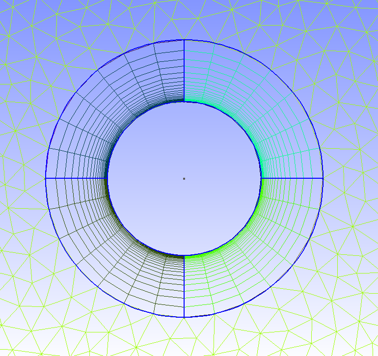

add_bezier ( * args, ** kwargs ) ¶ add_boundary_layer ( * args, ** kwargs ) ¶ add_bspline ( * args, ** kwargs ) ¶ add_circle_arc ( * args, ** kwargs ) ¶ add_curve_loop ( * args, ** kwargs ) ¶ add_ellipse_arc ( * args, ** kwargs ) ¶ add_line ( * args, ** kwargs ) ¶ add_physical ( entities, label = None ) ¶ add_plane_surface ( * args, ** kwargs ) ¶ add_point ( * args, ** kwargs ) ¶ add_polygon ( * args, ** kwargs ) ¶ add_spline ( * args, ** kwargs ) ¶ add_surface ( * args, ** kwargs ) ¶ add_surface_loop ( * args, ** kwargs ) ¶ add_volume ( * args, ** kwargs ) ¶ copy ( obj ) ¶ dilate ( obj, x0, abc ) ¶ extrude ( input_entity, translation_axis, num_layers = None, heights = None, recombine = False ) ¶Įxtrusion of any entity along a given translation_axis. Geometry base class containing all methods that can be shared between built-inĪnd occ. CommonGeometry ( env, init_argv = None ) ¶ If we want to close our cylinder we need to go back to Geometry > Add > Plane Surface, and if we need a Volume, as long as you have a closed domain you can go to Geometry > Add > Volume and finalize the solid cylinder.Common functions shared between the geo and the occ kernels. Furthermore, we see that there have been generated 4 surfaces in addition to the bottom surface we initially generated when creating the circle. Evidently, the numbering is a little odd as automatically there will be overlapping lines and surfaces which will be removed to avoid duplicates. The way the extrusion labels the lines is: top, right, left. The first line we selected to be extruded was line 1, and that gives us a pattern that will be useful whenever we are creating more complicated geometries that need to be parametrized. So far we have created all geometries by entering numbers one by one in our text editor but here we have used the GUI. Note that the blue numbers represent the line labels and the gray ones the surfaces. Here we’ll see a couple of interesting facts. Let’s extrude the lines that define our circle: You can extrude: Points, Lines and Surfaces, creating Lines, Surfaces and Volumes respectively. Depending on our modeling end goal, there are different types of extrusion. Going back to the circle example, we could just extrude it and create a cylinder. In 3D we will find other features useful such as: Translate, Rotate, etc. So far we have covered most of the features under Add in the Geometry node. It’s clear that the volume has been created when we select the Sphere to be a solid and will be described by Volume 30, which we have defined in our.

How can we know for sure that it is a solid volume? Go to the top menu, click Tools > Visibility and a window with all the defined Elementary Entities will pop up. Now, in Gmsh you only see line and surfaces even if you have created a volume. Finally we can create a volume, which in this case will be our solid geometry. The Line Loop feature groups all the lines, which in this case are defined by the Circle (arches), and then to create the surfaces, we use the Ruled Surface feature which is meant to create surfaces from curved geometries. The first part of the script will be omitted as it’s the same as the one found in the circle. Whenever we work in 3D, we can work with a solid domain or just with a shell surface. dat file:Īs we see above, we have also included another flag. In the sphere case we can use the very first version of our circle as we will only need to create two additional points to create 3 intersecting circles.
#Gmsh extrude layer progression how to#
This way we will showcase how to create a sphere. We will start with the circle we have created in our previous post “ Basic 2D Geometry Creation Using Gmsh“. Although, we have already covered the fundamentals of 2D geometries with Gmsh and the generation of the 3D geometry is quite similar (or identical), I want to mention a couple of attributes that might be of interest when modeling unbounded domains, i.e. This basic tutorial covers 3D geometries.


 0 kommentar(er)
